
- ISO FITS AND TOLERANCES CHART MANUAL
- ISO FITS AND TOLERANCES CHART SERIES
- ISO FITS AND TOLERANCES CHART FREE
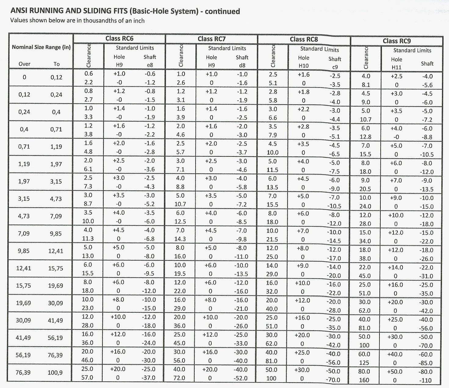
For example, in the case of driving shafts where a single shaft may have to accommodate a variety of accessories such as couplings, bearings and collars, it is preferable to maintain a constant diameter for the permanent member, which is the shaft, and vary the bore of the accessories. In some circumstances, however, it may in fact be preferable to employ a shaft basis. Once he has installed the necessary tooling and gauging facilities, he can combine his selected hole and shaft tolerances in different ways without any additional investment in tools and equipment.įor example, if it is assumed that the range of fits shown in the table has been adopted but that, for a particular application the fit H8-f7 is appropriate but provides rather too much variation, the hole tolerance H7 could equally well be associated with the shaft f7 and may provide exactly what is required without necessitating any additional tooling.įor most general applications, it is usual to recommend hole-basis fits, as, except in the realm of very large sizes where the effects of temperature play a large part, it is usually considered easier to manufacture and measure the male member of a fit, and it is thus desirable to be able to allocate the larger part of the tolerance available to the hole and adjust the shaft to suit. It is clearly impossible to recommend selections of fits which are appropriate to all sections of industry, but it must be emphasized that a user who decides upon a selected range will always enjoy the economic advantages this conveys. It should be noted, however, that this table is offered only as an example of how a restricted selection of fits can be made. For this publication, reference is still made to BS 4500 as are the data sheets reproduced on the following pages.
ISO FITS AND TOLERANCES CHART SERIES
However, the information contained in BS 4500 is identical to that in the BS EN 20286 series and many engineers still use the BS 4500A (hole basis) and BS 4500B (shaft basis) data sheets because they are easier to read and include diagrams of the relationships between a hole and a shaft for commonly applied fits in the clearance, transition and interference classes. Both of these Standards have replaced BS 4500 (which has been withdrawn by BSI). BS EN 20286 Part 2 provides tables of standard tolerance grades and limit deviations for holes and shafts.
ISO FITS AND TOLERANCES CHART MANUAL
Maguire CEng, MIMechE, Mem ASME, REng.Des, MIED, in Manual of Engineering Drawing (Fourth Edition), 2012 Selected ISO Fits – Hole Basis (Extracted from BS 4500)īS EN 20286 Part 1 describes the ISO system of limits and fits, providing the basis of tolerances, deviations and fits. 1Īxial setting is not very critical for the single spring design of seal ☒.5 mm (☐.100 in): for the multi spring design however, it is limited to about ☐.5 mm (☐.020 in).Ĭolin H. Axial run out for the non-sliding seal ring is about the same order as the above but for speeds higher than 3000 rev/min a useful guide is 0.0002 mm/mm of dia (0.0002 in/inch of dia). Permissible eccentricity for O-ring and wedge fitted seals varies from 0.10 mm (0.004 in) TIR at 1000 rev/min to 0.03 mm (0.001 in) TIR at 3000 rev/min: rubber bellows fitted seals accommodate 2 to 3 times these values. Seal face surface finish depends very much on the material – about 0.25 μm R a (10μ in cla) for carbon/graphite to about 0.05 μm R a (2 μin cla) for hard faces. Seal face flatness is usually better than two or three helium light bands (0.6 or 0.9 μm) per 25 mm of working face diameter.
ISO FITS AND TOLERANCES CHART FREE
Where the sliding packing passes over the shaft a 10° chamfer and lead-in, free from burrs should be provided. Shaft surface finish should be better than 0.8 μm R a (32 μin cla) except where PTFE wedge packings are used which require better than 0.4 μm R a (16 μin cla) and preferably a corrosion resistant surface (Stellite) on which to slide. Shaft tolerances should be within ☐.05 mm (☐.002 in) and where PTFE wedge packings are used must be round within 0.01 mm (0.0005 in).

In Tribology Handbook (Second Edition), 1995 Installation and allowable malalignments


 0 kommentar(er)
